(Download) UPSC IES Exam Paper - 2018 "Civil Engineering Paper - 1"
![]()
(Download) UPSC IES Exam Paper - 2018 "Civil Engineering Paper - 1"
Exam Name: Engineering Services Exam (IES)
Paper : Civil Engineering Paper - 1
Year: 2018
File Type: PDF
CIVIL ENGINEERING
Paper I
Time Allowed : Three Hours
Maximum Marks : 300
QUESTION PAPER SPECIFIC INSTRUCTIONS
Please read each of the following instructions carefully before attempting questions.
Answers must be written in ENGLISH only.
There are EIGHT questions divided in TWO Sections.
Candidate has to attempt FIVE questions in all.
Questions No. 1 and 5 are compulsory and out of the remaining, THREE are to be attempted choosing at least ONE question from each Section.
The number of marks carried by a question/part is indicated against it.
Answers must be written in the medium authorized in the Admission Certificate which must be stated clearly on the cover of this Question-cum-Answer (QCA) Booklet in the space provided.
No marks will be given for answers written in a medium other than the authorized one. Wherever any assumptions are made for answering a question, they must be clearly indicated. Diagrams/figures, wherever required, shall be drawn in the space provided for answering the question itself.
Unless otherwise mentioned, symbols and notations carry their usual standard meanings. Attempt of questions shall be counted in sequential order. Unless struck off, attempt of a question shall be counted even if attempted partly. Any page or portion of the page left blank in the Question-cum-Answer Booklet must be clearly struck off.
SECTION 'A'
1.(a) (i) List out at least eight tests required to determine the suitability of stone for engineering use.
(ii) Briefly explain the purpose and the procedure for Attrition Test on stone.
1.(b) A very long steel drill pipe got stuck in hard clay at an unknown depth. The drill pipe was applied a large upward force and observed that the drill pipe came out elastically by 500 mm. It was also observed that there was elongation of 0.04 mm in a gauge length of 200 mm. Estimate the depth of hard clay bed. Following consideration may be taken into account:
Resistance offered by all material/elements may be taken as zero.
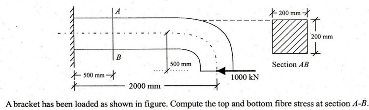
1.(c)
1.(d) A beam AB is simply supported over a span of 15 m. An u.d.l of 25 kN/m intensity and 5 m length moves over the beam from end A to B. Draw the influence line diagram for bending moment and shear force at section C located at 6 m from end A. Hence calculate the maximum bending moment and she force at section C.
1.(e)
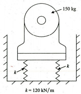
A motor of 150 kg mass is supported by four springs as shown in figure. Each of the springs has a stiffness of 120 kN/m. The unbalance of the rotor is equivalent to a mass of 40 g located at 150 mm from the axis of rotation. The motor is constrained to move vertically. Find
(i) the speed of motor at which resonance will occur
(ii) the amplitude of vibration of the motor when the speed is 1000 rev./m. 12
2.(a) (i) List out eight chemical ingredients of Portland cement and briefly explain their functions.
(ii) What are Bogue's compounds ? Briefly mention their functions.
2.(b) A square bar (50 mm x 50 mm cross-section) of 100 mm length is subjected to an axial compressive load of 10 kN. Calculate the change in volume of the bar, if all lateral strains of the bar are prevented by a uniform pressure on its four lateral faces. Calculate this pressure value and the change in volume. Also calculate the value of bulk modulus K and shear modulus G for the material of bar. Following parameters may be used if required. 1. E= 2x10⁵ N/mm2 2. u = 0.25
2.(c)

The frame shown in figure is fabricated using members with cross-sectional areas as given below:
Diagonal members = 2000 sq. mm
Other members = 1000 sq. mm
E for the material of members = 2x10⁵ N/sq.mm
Member AC was fitted last and the length of the member was 1 mm short.' Determine the forces developed in the members when AC was pulled and fitted in position.
3.(a) (i) Briefly explain Thermoplastic and Thermosetting materials.
(ii) List out six differences between them.
(iii) Briefly explain manufacture of Aluminium and state at least six physical and mechanical properties of Aluminium.
3.(b) In a steel flat plate a state of plane stress available. Calculate o, and principal stresses if ox= 140 N/mm2, u = 0-25, Try = 40 N/mm2, €, = -3-6x10⁻⁴ and E = 2x10⁵ N/mm2.
3.(c)

A beam of unsymmetrical I section shown in figure is simply supported over a span of 8 m. It carries a uniformly distributed load of 20 kN/m over the entire span. Draw the sketch for shear stress variation across the depth of the cross-section located at a distance of 3 m from left end A.
4.(a) A single solid circular shaft 400 mm diameter running at 200 RPM, is to be replaced by two hollow circular shafts of equal size running at 100 RPM and developing 50% additional power. The internal diameter of hollow shaft may be taken as one third of their external diameters. If the working stress of the new shaft is 30% greater than that of the former, find the external and internal diameters of the hollow shafts.
4.(b)
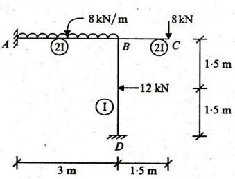
Analyse the frame shown in figure by slope deflection method and draw the B.M.D. and S.F.D.
4.(c) (i) Distinguish between Flexibility Method and Stiffness Method used for analysis of structures.
(ii)

Briefly explain the procedure and then develop the stiffness matrix for the beam element shown in figure with respect to the degrees of freedom 1, 2 and 3. The cross-sectional area A and flexural rigidity El are constant for the beam.
Study Material for IAS (UPSC) General Studies Pre. Cum Mains
SECTION 'B'
5.(a) Find the shape factor of a triangular section of base b and height h for bending about an axis parallel to the base.
5.(b) A construction project has the following characteristics :
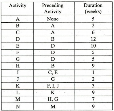
(i) Draw a network for this project, (ii) Find various paths and the
critical path as well as the project completion time
(ii) Prepare an activity schedule showing Earliest Start time, Earliest Finish
time, Latest Start time,Latest Finish time and float for each activity.
(iv) Will the critical path change if activity G takes 10 weeks instead of 5
weeks ? If so, what will be the new critical path ?
5.(c)

An isolated footing is transferring load from a column (300 mm x 300 mm) as shown in figure.
Arrange the plan dimensions of footing so that there will be uniform soil pressure intensity.
Following parameters may be used.
1. Column size : 300 mm x 300 mm
2. Safe Bearing capacity : 100 kN/m2
3. Dead weight of footing and soil weight over it may be taken as 10% of
vertical load of column.
5.(d) An ISMB 400 beam is spliced at a section carrying factored bending moment of 120 kNm and factored shear force of 80 KN. The splice is to be designed so that the flange splice will carry the bending moment and the web splice will carry the shear force. Field welding with 8 mm fillet will be used. Determine the size of 100 mm wide flange plate using the following data :
tf= 16 mm; tw = 8.9 mm and bf= 140 mm.
6.(c)
7.(a) Write in brief the principles of Dragline and Clamshell used as excavation equipments, the detail of their components and neat sketches showing their parts. How both the equipments can be compared ?
7.(b)
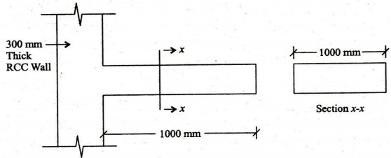
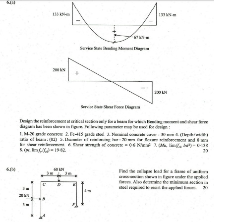
Design a cantilever slab shown in figure for flexure only. Sketch the reinforcement also. Following parameters may be used for design, applying different checks and detailing the reinforcement : 1. Span to effective depth : 10 (maximum) 2. Mild exposure condition : Nominal concrete cover 200 mm 3. 2-0 Hours of fire resistance : Nominal concrete cover 25.00 mm 4. Maximum live load : 30 kN/m2 5. Load combination : 1:5 ~ Dead load +1.5 x live load 6. Effective length : length to the face of support plus half the effective depth 7. Grade of concrete M-20 8. Grade of reinforcing steel Fe-415 9. Unit weight of RCC: 25 kN/m3 10. Development length in Tension : 48 x diameter of reinforcing bar 11. Development length in compression : 37 x diameter of bar 12. Mini of total cross-sectional area 13. Maximum spacing of main reinforcement : 3 x effective depth 14. Maximum spacing of distribution reinforcement: 5 x effective depth 15. Diameter of main reinforcing bar : 10 mm 16. (Mu, lim/fck bd2) = 0.138 17. (pt, lim fy/fck) = 19.82.
8.(a) (i) What is a work breakdown structure in Construction Project Management ? Define and explain in brief. Further, how Work Breakdown Structure is classified into different levels for making the job convenient ? Explain with an example.
(ii) What is Resource Leveling in Construction Project Management and how it is different than Resource Loading ?
8.(b)
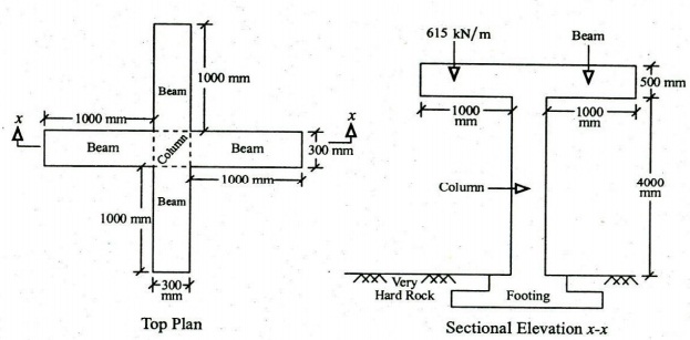
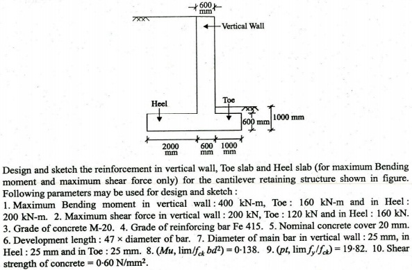
A square column (500 mm x 500 mm) carries load from two beams, which are mutually perpendicular as shown in figure. Overhang portion of beams carry a total load of 615.0 kN/m (include self-weight). Design the column at top of footing level. Footing is fully embedded in very hard rock. Beams are restrained against rotation at Beam-column junction. The minimum eccentricity is less than 0.05 times the lateral dimension of column. Sketch all details required at column cross-section.
Use: M-20 grade concrete, Fe-415 grade reinforcing bars, Appropriate coefficient form 1-0/1-20/ 1.50/2.0, Main reinforcing bar : 32 mm diameter.
8.(c) Determine the ultimate bending moments and forces due to vertical and horizontal loads that act on a simply-supported gantry girder. Use the following data :
1. Simply supported span = 6 m 2. Distance between crane wheels = 3.6 m 3. Self-weight of girder = 1.5 kN/m 4. Maximum crane wheel load (static) = 220 KN 5. Weight of crab/trolley = 60 KN 6. Maximum hook load = 200 KN
Take impact factor of 25% and assume double flanged wheels e = 0.15 m while the girder depth, D= 0-60 m.