(Download) UPSC IES Exam Paper - 2018 "Mechanical Engineering
Paper - II"
Exam Name: Engineering Services Exam (IES)
Paper : Mechanical Engineering Paper - II
Year: 2018
File Type: PDF
MECHANICAL ENGINEERING
PAPER-2
Time Allowed : Three Hours
Maximum Marks : 300
QUESTION PAPER SPECIFIC INSTRUCTIONS
Please read each of the following instructions carefully
before attempting questions
There are EIGHT questions divided in two Sections.
Candidate has to attempt FIVE questions in all.
Question Nos. 1 and 5 are compulsory and out of the
remaining, any THREE are to be attempted choosing at least ONE
from each Section.
The number of marks carried by a question/part is indicated against it.
Wherever any assumptions are made for answering a question, they must be
clearly indicated.
Diagrams/Figures, wherever required, shall be drawn in the space provided for
answering the question itself.
Unless otherwise mentioned, symbols and notations have their usual standard
meanings.
Psychrometric Chart is given in Page No. 8.
Attempts of questions shall be counted in sequential order. Unless struck
off, attempt of a question shall be counted even if attempted partly.
Any page or portion of the page left blank in the QCA Booklet must be clearly
struck off.
Answers must be written in ENGLISH only.
SECTION-A
Q1. (A) (i) A flue pipe in a furnace system is rigidly
attached to the furnace wall at P, as shown in the figure below. Compute the
moments at points P1 and P2 when a force of 300 N is
acting at the end of the pipe.

(ii) Consider a solid block of mass 'm' resting on a
horizontal surface. When the mass is subjected to a horizontal force 'P' it will
experience a frictional force resisting the motion. Draw and show the variation
of frictional force F vs. applied force P even if it continues to shift from no
motion (static friction) domain to motion domain (kinetic friction).

(B) Draw and show the bending moment diagram and shear force
diagram of a beam of length 'L' subjected to a uniformly distributed loading for
the following boundary conditions:
(i) Cantilever beam
(ii) Simply supported beam
(iii) Beam with both ends fixed
(iv) Beam with one end simply supported and a propped support at 1/4th L from
the other end
(C) (i) Distinguish and differentiate between machine and
mechanism. Define the term Inversion of a kinematic chain.
(ii) Discuss about the possible inversions (with figures) of
a four bar chain.
(D) Derive the equation for the resultant unbalanced force at
any instant of a reciprocating mass of a slider crank mechanism.
(E) In a pair of mating spur gears, the pitch-diameter of
smaller gear is 120 mm. The pair is of standard gear involute having module as
8. If the transmission ratio between the gears is 4:3, then find out
(i) Number of teeth on gear,
(ii) Number of teeth on pinion,
(iii) Addendum,
(iv) Dedendum,
(v) Whole depth, and
(vi) Clearance.
Q2. (A) Compute the velocity and acceleration of the slider
in the quick return mechanism shown in the figure below, if the crank rotates at
30 rpm.
(B) (i) Draw and show the variation of centrifugal force and
controlling force of a governor.
(ii) Define Stability, Sensitivity, Isochronism governor. and
Hunting in a
(C) The data for 2 sets of spur gears are given below :

Check for the occurrence of Interference. If it occurs, what
is the pressure angle to correct it?
(D) (i) A single degree of freedom system is subjected to an
external harmonic force F(t) = F, sin wit. Define magnification factor (MF) and
plot it as a function of damping factor as it varies with respect to frequency
ratio.
(ii) A machine part having a mass of 2.5 kg vibrates in a
viscous medium. A harmonic exciting force of 30 N acts on the part and causes a
resonant amplitude of 14 mm with a period of 0.22 seconds. Find the damping
coefficient.
Q3. (A) (i) Define, discuss and differentiate :
(A) Centers of mass vs Centroid
(B) Mass Moment of Inertia vs Area moment of inertia
(C) Centroid of Lines, Areas and Volumes
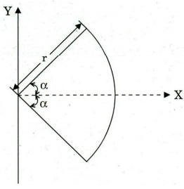
(ii) Locate the centroid of a circular arc as shown in the
figure below:
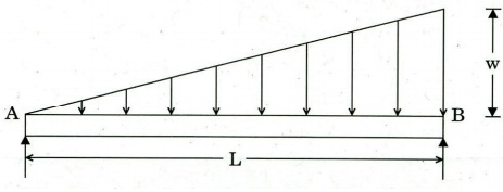
(B) Draw the Shear Force Diagram and Bending Moment Diagram
of a simply supported beam carrying a uniformly varying load from zero at one
end to 'w' per unit length at the other end. Compute the maximum B.M and its
location.
(C) (i) Three children are standing on a 5 m x 5 m raft as
shown in the figure below :
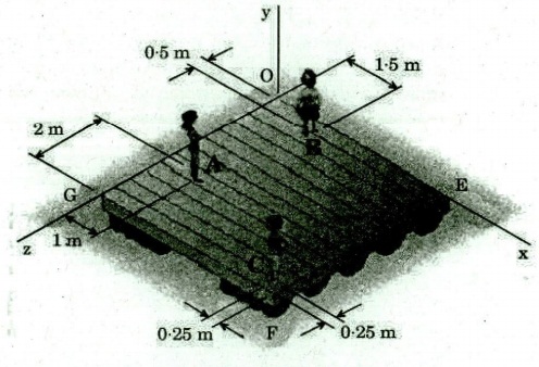
The weights of the children at points A, B and C are 375 N,
260 N and 400 N, respectively. Determine the magnitude and the point of the
resultant of their weights.
(ii) In a two dimensional system acted by various forces as
specified below :
Draw the free body diagram and equation defining them.
(D) Two shafts of the material and of same lengths are
subjected to same torque. If the first is of a solid circular section and the
second shaft is of hollow circular section, whose internal diameter is 2/3 of
the outside diameter and the maximum shear stress developed in each shaft is the
same, compare weights of the shafts.
Q4. (A) Differentiate between uniform pressure and uniform
wear theory. What would you conclude, about the effect over friction radius,
under following two conditions of operation of a clutch, considering uniform
pressure theory and uniform wear theory in both the conditions.
(i) Outer Radius - 100 mm
Inner Radius – 90 mm
(ii) Outer Radius – 100 mm
Inner Radius - 25 mm
(B) Design a flywheel for a single cylinder four-stroke
diesel engine, made of cast iron, whose allowable strength is 20 MN/m2. The
engine is running at a speed of 1400 r.p.m. and producing 5 kW of power. Maximum
peripheral speed of the flywheel may be up to 24 m/sec. Coefficient of
fluctuation of energy may be taken as 2.2 and coefficient of speed fluctuation
as 0.015. Density of cast iron may be taken as 7000 kg/m3. (The effect of
overhang of the flywheel on the end may be neglected.)
(C) Three M20 bolts are used to connect a steel plate with a
channel section structural member as shown in the figure. The material of the
bolt is 50C4 with o, = 660 MPa and oy = 460 MPa. Determine the factor of safety,
if the plate carries a load of 25,000 N at its end. Take area of M20 bolts as
245 mm2


